Want some sick Spire Starter swag? Register to win by December 15, 2025!
Let us know what size you’d want, the address to send it to, and your email and we’ll let you know when it’s on its way if you’re 1 of the 10 lucky winners.
Details: No purchase necessary to win. 1 entry per person. 10 winners will be randomly selected from entrants. Must have USA shipping addresses; no international shipments.
Giveaway Ended!
Winners were notified by email and orders sent to printers 12/15/2025. Thanks for entering!
Erin McDermott’s invited talk at SPIE’s Optical Engineering + Applications conference August 2025 is now available online here: https://doi.org/10.1117/12.3066535
From vast experience working in industry — from large manufacturers to nimble hardware startup teams for more than 20 years — Erin noticed a dangerous disconnect between how optical science is taught and what it’s like to develop optical systems in the real world. Bad assumptions, misunderstandings, and cross-disciplinary communication breakdowns frequently lead to problems, which fresh engineers are not warned about. These can materialize as system failures, delayed development, extra prototyping iterations and failures to deliver that may result in millions of dollars of losses!
Erin’s talk and accompanying white paper highlight specific examples of these many surprise pitfalls. Moreover, she conveys a new type of thinking necessary to succeed in high volume manufacturing settings. Plugging in numbers into a memorized equation to neatly get the exact correct answer on a multiple choice test is not the solution! The real world is messy. Following a robotic series of steps to engineer “the right way” often leads to disaster, because each individual project is more complicated than an academic rubric can encompass. Different industries, materials, manufacturing methods, and engineering teams can each bring new considerations to how the optical engineer must work to successfully get their 2D simulated optical designs functioning in 3D on the bench.
Theory vs. manufacturing reality: bridging the disconnect in nonimaging optics
ABSTRACT Nonimaging optics is often presented in academic settings as a clean, linear process: design an optic, add tolerances, and hand it off to be manufactured. Yet, in practice, especially in high-volume manufacturing, the workflow is rarely this smooth and often requires a root cause analysis phase when mysterious errors emerge. This paper presents a series of informal, real-world case studies that illustrate the gap between academic learnings and the types of techniques and mindset necessary to engineer for unpredictable manufacturing environments. Specific examples drawn from Synopsys LightTools, Ansys Speos, and Breault’s ASAP demonstrate how simulation defaults, software limitations, and scatter modeling peculiarities can produce misleading results if applied without comparing to real-world measurements. Additional sections highlight how errors and misunderstandings made by other departments such as manufacturing, mechanical engineering, and even accounting can lead to system failures that an optical engineer will often be tasked with untangling. This paper offers cautionary tales and example solutions to help prime engineers’ thinking on how to prevent failures. Or, when the inevitable happens, to inspire them to let their imaginations soar while brainstorming root causes.
We just added this illuminance calculator to the site – but it’s important to also lay out All The Grains of Salt you should take it with!
It only works for estimating lux in certain cases, and, like all rough estimates, it should never be used for coming up with design parameters for your system. It shouldn’t be used for other extremely critical determinations, either!
See below for more context on the inverse square law that this thing is based on. It discusses an example (sunlight in space bouncing off flat mirrors) where this law doesn’t work well because the rays are almost parallel.
In contrast, it DOES work well for things like bare LEDs where light is coming out in a really wide angle from a really small surface area.
For easy access to this calculator in the future, see the footer of this site.
Here’s a simplified discussion on why inverse square law does not work to disqualify Reflect Orbital’s technology concept, as was posited by a Twitter/X user.
If the rays (or beam angle) of the light you want to use the illuminance calculator for also have a parallel distribution, or even just a really narrow beam spread, the calculator won’t be useful for you.
On the other hand… If the light you want to really roughly estimate has a very, very wide beam angle or a Lambertian distribution (like bare LEDs), it might be pretty close.
In any case, it’s best to consult an expert!
Book your free, 20-minute Zoom consultation here if you’d like to explore what we can accomplish in an optical engineering contract.
Do YOU have wild stories about CLUSTERf&@!s in engineering/manufacturing/physical product development?
(I bet you do if you’ve been in the game long enough.)
Would YOU want to anonymously (or not anonymously) share them for a collection while anonymizing/protecting company and product names?
If you bring the stories over on Odd Engineer, Spire Starter will publish them in a collection!
Current working title: “Engineering SNAFU, Volume 1: Stories of Noteworthy Atrocities at Factories Unveiled.” And for any entry that makes it into the book, we’ll happily send you a hard copy.
Remember, if you don’t need to personally remain anonymous because you have enough clients or past employers to obscure the identity of stakeholders in your story (or stories) this can be excellent marketing content!
2. Read and agree to the “Submission Terms and Agreement” on the page.
3. Complete the form at the bottom of the page. The first lines for name and email address will be only used to communicate internally, not for publishing, and need to be real. The following lines for name and title, current company, marked “for publishing purposes” will be used for published content and can be “anonymous” if you wish. (We’ll double-check this with you before publishing.)
4. Do it by the deadline of October 31, 2023.
How to Read LED Datasheets: the Parts Optical Engineers Care About for Illumination/Lighting Design
Simple breakdown of LED Datasheet terms important for LED lighting design.
To schedule a free consultation to discuss 🗣️👩💻👨💻🧑💻 what we can do in a contract to optimize YOUR non-imaging 💡 optical system,
•Most important data for optical engineers that’s not on the datasheet! 😲 — ray files !
We got enough questions on optical engineering education that we decided to do a whole thing on it. And here it is!
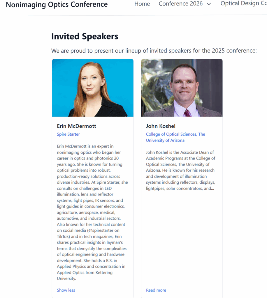
Last year, our Director of Optical Engineering, Erin M. McDermott, published an article and video on SolidSmack about the basics of what optical engineering is (since so many don’t know).
Since then we’ve been getting pinged, not just by the intended audience of other hardware engineering disciplines, but by students who want to jump into optics and photonics careers.
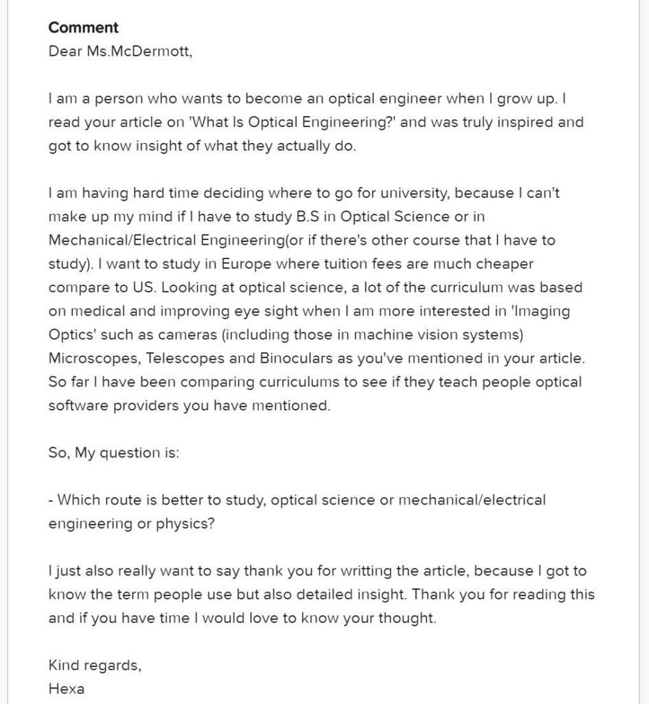
The latest is a student named Jung-Mundi, who on LinkedIn goes by Hexa Koo. (Huge apologies for both the pronunciation of these names and the ignorance about this individual’s gender!) Jung-Mundi gave permission to publish his/her messages to me, which follows:
For Erin’s full reply, you can watch this video below:
Some Takeaways
No matter what specialties you’re interested in, these tips apply to anyone interested in an engineering career.
PRACTICAL EXPERIENCE — whether through internships or (even better!) a comprehensive co-op program — can hugely enhance your ability to get a great job after graduation.
ELECTIVES IN COMPLEMENTARY DISCIPLINES — take a look not just at the classes available in your specific curriculum, but also in the offerings of complementary engineering/science tracks. If you’re interested in machine vision from the optics side, it would behoove you to learn about it from the computer science, mechanical engineering, and electrical engineering sides, too! What good stuff is available outside your major and how many electives do you have to play with?
STUDY ABROAD – we’d highly recommend this one for both giving you an edge in your field and broadening your network. It also says something to an employer if you can handle being routinely thrown into strange, foreign situations. (Something tells us Jung-Mundi already has some international travel under his/her belt, though…)
IN-PERSON CONNECTIONS – if you can, reach out to prospective professors, both online and in person! In both academics and later professional life, personal connections are super important. When people meet you and like you, they’re more likely to help you out in extraordinary ways. You also learn a lot more interesting details when you show up and ask questions in person! A LOT more. A lot. So much. Infinitely more stuff, even. Can’t emphasize this enough.
Optics and Photonics-Specific Advice
Jung-Mundi had some specific questions about optics education. He/she noted that most of the curricula she came across was biology/eyeball focused, but these weren’t the types of classes she was interested in. She wanted to play with the equipment that had nothing to do with eye health.
Other Degrees Not “Optical Science” Might Be Right For You – Depends on Your Aims and the Specific Universities. Jung-Mundi wondered if she was barking up the wrong tree with looking at a purely optical science B.S.. Again, though, it depends on each university’s offerings and available electives. In one university, it might be best to get their Optical Science degree. In another with a strong optical science department, it might actually be better to get an Engineering Physics or Electrical Engineering or Computer Science degree and heavily fill up electives with optics coursework. Play around with ways you can fill up each curriculum and see what matches your interests best. HOWEVER: if you want to be the guy who builds the microscope, or builds the camera, instead of the person who uses or adapts those things in other applications, you probably want the Optical Science B.S..
Optical Simulation Software Instruction – unless you are taking very detailed courses on optic design, you might not come out of your education with any optical simulation software proficiencies to put on your CV. So if you want to be the guy who builds the telescope, you definitely want to ask universities about this part. The more you can put on your resume, the better. However, if you have to pick just one for imaging optics, we’d recommend Zemax. This is the software you’d statistically be most likely forced to use when jumping into a new corporate job.
What is the “Best” University for Optical Science – in Europe, we have no idea what holds the most clout. In the United States, the reigning view is that University of Rochester is considered top (it was the first university to offer an optical science program in the United States, but is also where our Director of Engineering was born, so there’s some bias there), with University of Arizona close behind (if not equal depending on your geographical proximity), then there’s a university in Florida we’ve heard rumors of where you can also get a degree in optics. If you’re not trying to, say, specifically make camera lenses for Canon, however, this makes little difference to your career. Outside of those types of jobs, the managers looking for someone specifically coming from University X tend to simply not understand the field enough in order to come to their own conclusions about an individual’s ability. We’ve seen plenty of grads from “top” institutions who in the real world can’t deliver – whether you’re talking business school or in finding fast, creative solutions to technical problems. At Spire Starter, we value more things like: past technical accomplishments and experience, ability to find creative solutions and look at problems from new angles, flexibility, and general ability to follow-thru. If you’re smart, tenacious when fixing technical problems, and have some degree of interpersonal aptitude, those are the things that put you leaps and bounds above other engineers and scientists in our view!
If you have other tips and feedback for this student – or other students interested in optics and photonics in general – we’d love to hear from you! This is especially so if you have some Europe-focused insight. Feel free to comment here, on the ELE Optics Community forum, or on the LinkedIn post.
And be sure to check out the other stuff offered at the ELE Optics Community page! There is the opportunity to ask your own questions of other optics professionals, and an excellent podcast featuring the experiences of other optics pros. That’s some niche stuff right there.
Got other questions that you’d like answered in laymen’s terms? Drop us a line on the Contact Form and we’ll be happy to help you out!
Surprise! 🤯Your Company website is *not* about You! or if it is, it shouldn’t be I talk with a lot of
business owners and
freelancers that ask advice about
how to market themselves.
Usually, they start with
this totally wrong approach,
📢 “I/we provide dynamically dynamic excellent resources to effectively be excellent for excellence and dynamycims sake, delivering gobally world-changing productivity and success”
WTAF? 🤡
Your clients truly
do not give a 💩
about those words.
If they are in the market for your services,
they just want to know if:
➡️you can fix their problem.
🛑 period.
If they do ask for a CV, it’s because they are incompetent about your specialty and need a crutch to judge your aptitude:
🤨 “well did they go to the uni I was told by someone else was #1 for this discipline?”
🤔“well did they get hired by a company that gets a lot of headlines in TechCrunch, so I can let Company X’s evaluation of their competence stand in for my own?”
Types of things they *ACTUALLY* need to know:
✅that you creatively solved problems 🙌related to theirs (and can again)
✅that you can teach 👩🏫them stuff (read: ADD VALUE) right away, even on your homepage
✅ that you can be flexible 🖖 (if you can) around other restrictions their projects might impose such as: 😩them not completely understanding their own system needs yet, 😩tight timelines, 😩budgetary restrictions, 😩their lack of hardware and sw tools, specialized vendor connections, etc
Your company website should be about Your *Clients*!
Stray light is a problem that pops up in all sorts of optical systems. This is any light that goes where you don’t want it to.
This could cause glare in illumination systems, or it can degrade image quality in imaging systems. Stray laser light can cause some serious damage depending on how powerful the laser is! In automotive lighting, stray light can cause headlamps to fail government inspections. In sensor systems, sometimes stray light can come from something totally outside the optical system you design — like ambient light coming through a window.
Optical simulations can be used to figure out where offending stray light rays come from and bounce to. Simulations can also be used to figure out the best fix for stray light issues — trying out different solutions before anything is even prototyped.
Specular is just a fancy way of saying shiny. It means a surface is not rough, but smooth and reflective like a mirror.
A higher level description is that the light that hits a specular surface doesn’t reflect in a bunch of directions; light bounces off a surface (reflected ray) at the same angle as it hits the surface (incident angle). Of course, perfectly specular surfaces don’t typically exist in reality . . . but they’re often fine approximations in simulations (depending on application).
Reflex is the term used to describe the optical structures on those plastic, colored reflectors you see on cars and bicycles. Yeah, that has a name! And you know it now.


